Wireless Telephony And Alternating Currents
Chapter XVIII. Wireless Telephony And AlternatingCurrents.
The wireless telephone can be best understood by comparing it with the common telephone. When the latter is in use, a direct current flows continually through the instrument. (See Arts. 312-316.) When a person speaks into the transmitter, the sound waves of the voice cause the diaphragm to vibrate, this action causes rapid changes in the resistance of the transmitter, which in turn causes the direct current to fluctuate just in step with the pulses of the voice waves. This fluctuating direct current passes through the primary of an induction coil, producing in the secondary an intensified alternating current. This passes over the line wires to the receiver where it produces[Pg 461] variations in the magnetic field affecting the receiver diaphragm, causing the latter to reproduce the voice of the person speaking in the transmitter. Now to make the comparison clear, two facts must be noted with regard to the wire telephone: first, there must be an action in the transmitter which causes variations in a current through the instrument; second, this fluctuating current produces a more intense alternating current which flows over the line and affects the receiver diaphragm, producing there sound vibrations of greater intensity than those used at the transmitter. This added energy comes from the current flowing through the transmitter. The case is analogous to that of an electric bell. The armature of the bell vibrates with greater energy than is required to push the button, the extra energy being derived from the battery.
426. The Action of the Wireless Telephone.?In the wireless telephone we have a continuous stream of electric waves of high frequency. (See Fig. 425A.) This stream of electric waves corresponds to the current that flows through the transmitter in the wire telephone. These waves are of such high frequency that even though we had a receiver diaphragm vibrating in step with the waves, we could not hear the sound because the human ear cannot hear a sound which consists of more than about 40,000 vibrations per second. The sound waves act upon this stream of waves very much, as in the wire telephone, the transmitter acts to modify the line current. The impulses caused by the voice are much slower than the electric waves first mentioned and these slower impulses are reproduced in the receiver. Not only are these slower impulses reproduced but they are amplified, that is, produced with greater energy than the impulses impressed on the stream of waves. Fig.[Pg 462] 425A represents as nearly as is possible in a diagram the continuous stream of electric waves. Fig. 426B, represents the impulses produced by the sound alone, and Fig.[Pg 463] 426C, shows how these voice impulses are impressed on the stream of waves.
 Fig. 425.?A, unmodified high frequency waves; B, waves of voice frequency; C, high frequency waves modified by waves of voice frequency.
 Fig. 426.?Vacuum tube, transmitting type. (Western Electric Co.)
Fig. 427.?Vacuum tube, receiving type. (Western Electric Co.)
 Fig. 428.?Diagram of wireless telephone transmitting set.
427. The Vacuum Tube or Audion.?The device by which all of this is accomplished is the vacuum tube. (See Fig. 426.) This tube contains three electrodes. First, a filament (F, in Fig. 428) which is heated by a current from a battery (B1, Fig. 428) and because it is heated, sends out a stream of electrons. Second, the plate which forms the anode of the circuit from battery, B2. This plate receives the electrons which are thrown off by the heated filament, hence a current flows through the circuit of B2; the discharge through the tube depending on the e.m.f. between the filament and the[Pg 464] plate. Third, a grid is placed between the filament and the plate and is connected to the secondary of the induction coil, the primary of which is connected to the transmitter. When the transmitter diaphragm is vibrating, the e.m.f. induced in the secondary of the induction coil causes a variation in the potential of the grid. This means a variation in the electric field between the filament and the plate. (See Fig. 428.) The changing electric field causes a variation in the discharge of electrons through the tube; the variation corresponds to the vibrations of the transmitter diaphragm. This produces a surging current of the frequency of the sound waves in the primary of the transformer (T, Fig. 428). The secondary of this transformer is connected to the antenn? (A) and the earth (E). By means of the transformer, rapid surgings are set up in the antenn? and these surgings produce a continuous stream of electromagnetic waves which goes out in space. (Like Fig. 426C.) These electromagnetic waves produce oscillations in the antenn? of a receiving station. The antenn? transmit the impulses to a tube (Fig. 427) which acts[Pg 465] as a detector, and makes possible the reproduction of the sound by an ordinary telephone receiver.
Fig. 428.?Diagram of wireless telephone transmitting set.
427. The Vacuum Tube or Audion.?The device by which all of this is accomplished is the vacuum tube. (See Fig. 426.) This tube contains three electrodes. First, a filament (F, in Fig. 428) which is heated by a current from a battery (B1, Fig. 428) and because it is heated, sends out a stream of electrons. Second, the plate which forms the anode of the circuit from battery, B2. This plate receives the electrons which are thrown off by the heated filament, hence a current flows through the circuit of B2; the discharge through the tube depending on the e.m.f. between the filament and the[Pg 464] plate. Third, a grid is placed between the filament and the plate and is connected to the secondary of the induction coil, the primary of which is connected to the transmitter. When the transmitter diaphragm is vibrating, the e.m.f. induced in the secondary of the induction coil causes a variation in the potential of the grid. This means a variation in the electric field between the filament and the plate. (See Fig. 428.) The changing electric field causes a variation in the discharge of electrons through the tube; the variation corresponds to the vibrations of the transmitter diaphragm. This produces a surging current of the frequency of the sound waves in the primary of the transformer (T, Fig. 428). The secondary of this transformer is connected to the antenn? (A) and the earth (E). By means of the transformer, rapid surgings are set up in the antenn? and these surgings produce a continuous stream of electromagnetic waves which goes out in space. (Like Fig. 426C.) These electromagnetic waves produce oscillations in the antenn? of a receiving station. The antenn? transmit the impulses to a tube (Fig. 427) which acts[Pg 465] as a detector, and makes possible the reproduction of the sound by an ordinary telephone receiver.
 Fig. 429.?View of wireless telephone set.
The vacuum tube in the transmitting circuit also amplifies the impulses, that is, the energy of the waves given out is greater than that of the impulses which produce them, the additional energy being derived from the battery sending current through the plate and filament. In operation, the filament and the plate are connected to a battery with a condenser (VC) and an inductance coil (I) in the circuit, as shown in Fig. 428. Photograph of a complete modern wireless telephone set is shown in Fig. 429.
Fig. 429.?View of wireless telephone set.
The vacuum tube in the transmitting circuit also amplifies the impulses, that is, the energy of the waves given out is greater than that of the impulses which produce them, the additional energy being derived from the battery sending current through the plate and filament. In operation, the filament and the plate are connected to a battery with a condenser (VC) and an inductance coil (I) in the circuit, as shown in Fig. 428. Photograph of a complete modern wireless telephone set is shown in Fig. 429.
[Pg 466]
429. The Magnetic Field of an Alternating Current.?The magnetic field of a direct current has been considered in Arts. 255-256. It has been shown to be arranged in circles about the conductor, according to the Right Hand Rule. (See Figs. 229 and 230.) These facts will help one to understand the following experiment:
 Fig. 430.?Arrangement of compasses about a wire carrying an alternating current.
430. Transformers.?The transformer has been described in Arts. 309-310. The principle of the transformer may be illustrated by the following experiment:
Fig. 430.?Arrangement of compasses about a wire carrying an alternating current.
430. Transformers.?The transformer has been described in Arts. 309-310. The principle of the transformer may be illustrated by the following experiment:
 Fig. 431.?Diagram of a transformer.
This experiment illustrates the construction and action of a transformer. In a commercial transformer, the two windings are on a closed magnetic circuit. (See Figs. 304 and 305, p. 346.) To keep the coils insulated, the transformer is placed in an iron "housing" and covered with oil. These "housings," or transformer cases are generally attached to poles near buildings in which alternating current is used.
Fig. 431.?Diagram of a transformer.
This experiment illustrates the construction and action of a transformer. In a commercial transformer, the two windings are on a closed magnetic circuit. (See Figs. 304 and 305, p. 346.) To keep the coils insulated, the transformer is placed in an iron "housing" and covered with oil. These "housings," or transformer cases are generally attached to poles near buildings in which alternating current is used.
431. Voltage Relation in a Transformer.?In the experiment described above, a bell was rung by an induced current produced in the secondary coil. The induced e.m.f. was less than the voltage of the primary coil partly because there was some magnetic leakage, but mainly[Pg 469] because there were fewer turns of wire on the secondary. In a commercial transformer the magnetic leakage is practically zero. In such a case, the ratio of the number of turns on the primary coil to the number on the secondary equals the ratio of the e.m.f. induced in the primary to the e.m.f. induced in the secondary. Suppose, for example, we wish to make a bell ringing transformer to use on a 110 volt lighting circuit, 10 volts being required for the bell; the secondary will then need one-eleventh of the number of turns of the primary. So that if 550 turns are on the primary, then 50 turns will be needed for the secondary. This will be a "step-down" transformer. On the other hand, suppose we wish to "step-up" the voltage as is done in a certain power station where the voltage of the generators is 6000 volts, the voltage being stepped up to 44,000 by means of large transformers. This means that the secondary coils have approximately 7-1/3 times as many turns as the primary.
432. Power Loss in a Transformer.?When the voltage is "stepped up" in a transformer, do we gain power? To answer this question we must remember that electric power does not depend on voltage alone but on the product of e.m.f. and current intensity. (See Art. 291.) By tests with a.-c. voltmeters and ammeters, we find that when the secondary e.m.f. is greater than the primary e.m.f., the secondary current intensity is less than that in the primary. It is also found that the power developed is less than the power received by the transformer, i.e., the "output" is less than the "input" as we would expect from the law of machines. The power loss is mainly due to the work required to reverse the magnetism, that is, to continually reverse the position of the iron molecules. (See Art. 205.) The energy lost in this manner is known as "core loss" since it occurs in the[Pg 470] iron core. The lost energy appears as heat. So much heat is developed in large transformers that special means of cooling are provided. In order to make the heat developed as small as possible, the cores are "laminated" (see Fig. 305, p. 346), that is, built up of thin sheets of iron, because if the iron cores were solid, the changing magnetic fields would induce electric currents in the iron cores, which would produce an excessive amount of heat with a correspondingly large power loss.
 Fig. 432.?Diagram of "bell-ringing" transformer.
433. Choke Coils and Inductance.?If we refer to Fig. 432 we see that the primary winding of the bell ringing transformer is connected across the line. This winding forms a closed circuit whether the bell is ringing or not. The resistance of this winding is small. Let us assume it to be one ohm. With a one ohm resistance connected across a 110 volt line we might expect a current of 110 amperes. This is certainly what we should get if we were to connect a one ohm resistance across a line having 110 volts direct. The primary would form a short circuit if the current were direct. But the fact is that practically no current flows through the primary winding when the bell is not ringing. Herein lies one of the important differences between alternating and direct currents. With an alternating current the primary winding of our transformer[Pg 471] acts as a choke coil and "chokes" down the current almost to zero. Let us see how this is done.
Fig. 432.?Diagram of "bell-ringing" transformer.
433. Choke Coils and Inductance.?If we refer to Fig. 432 we see that the primary winding of the bell ringing transformer is connected across the line. This winding forms a closed circuit whether the bell is ringing or not. The resistance of this winding is small. Let us assume it to be one ohm. With a one ohm resistance connected across a 110 volt line we might expect a current of 110 amperes. This is certainly what we should get if we were to connect a one ohm resistance across a line having 110 volts direct. The primary would form a short circuit if the current were direct. But the fact is that practically no current flows through the primary winding when the bell is not ringing. Herein lies one of the important differences between alternating and direct currents. With an alternating current the primary winding of our transformer[Pg 471] acts as a choke coil and "chokes" down the current almost to zero. Let us see how this is done.
 Fig. 433.?A circuit containing a choke coil.
Let Fig. 433 represent a choke coil. Since alternating current is used, the magnetic field is continually changing. Each turn of wire has its own magnetic field. The lines of force of turn number 1 expand and contract and as they do so they move across turns 2, 3 and so on. In like manner the lines of force from each turn of wire move across the other turns. In other words the coil is cutting its own lines of force. Now whenever an electric conductor cuts magnetic lines of force an electromotive force is induced in the conductor. There is then an e.m.f. induced in the coil by its own magnetic field. This induced e.m.f. on the whole opposes the applied e.m.f.; in the primary of our bell ringing transformer the induced e.m.f. opposes the e.m.f. of the line to such an extent as to reduce the current almost to zero. Inductance is the action of an alternating current in inducing an opposing e.m.f. in the coil in which the current is flowing. Since this opposing e.m.f. is induced in the coil by its own magnetic field this action is also called self-induction. In a transformer the action of the field of the primary upon the secondary is mutual induction; while the action of the field of the primary in choking the current in the primary itself is self-induction or inductance. A coil having a single winding and used to introduce inductance in a[Pg 472] circuit is called a choke coil. A choke coil inserted in a lamp circuit in series with the lamps dims the lamps because it reduces the intensity of the current.
Fig. 433.?A circuit containing a choke coil.
Let Fig. 433 represent a choke coil. Since alternating current is used, the magnetic field is continually changing. Each turn of wire has its own magnetic field. The lines of force of turn number 1 expand and contract and as they do so they move across turns 2, 3 and so on. In like manner the lines of force from each turn of wire move across the other turns. In other words the coil is cutting its own lines of force. Now whenever an electric conductor cuts magnetic lines of force an electromotive force is induced in the conductor. There is then an e.m.f. induced in the coil by its own magnetic field. This induced e.m.f. on the whole opposes the applied e.m.f.; in the primary of our bell ringing transformer the induced e.m.f. opposes the e.m.f. of the line to such an extent as to reduce the current almost to zero. Inductance is the action of an alternating current in inducing an opposing e.m.f. in the coil in which the current is flowing. Since this opposing e.m.f. is induced in the coil by its own magnetic field this action is also called self-induction. In a transformer the action of the field of the primary upon the secondary is mutual induction; while the action of the field of the primary in choking the current in the primary itself is self-induction or inductance. A coil having a single winding and used to introduce inductance in a[Pg 472] circuit is called a choke coil. A choke coil inserted in a lamp circuit in series with the lamps dims the lamps because it reduces the intensity of the current.
 Fig. 434.?Diagram showing graphically an alternating current with a "lag" of 30? behind its electromotive force.
Self-induction causes the current to lag, that is, the current does not quite reach its maximum at the instant the voltage reaches its maximum. Fig. 434 shows graphically an e.m.f. and a lagging current. In this figure the maximum current is shown following the maximum voltage at an interval of 30 degrees. In other words the armature in a two-pole field must turn 30 degrees from the position of maximum voltage before the current in the coil, where the self-induction occurs, reaches its maximum.
Fig. 434.?Diagram showing graphically an alternating current with a "lag" of 30? behind its electromotive force.
Self-induction causes the current to lag, that is, the current does not quite reach its maximum at the instant the voltage reaches its maximum. Fig. 434 shows graphically an e.m.f. and a lagging current. In this figure the maximum current is shown following the maximum voltage at an interval of 30 degrees. In other words the armature in a two-pole field must turn 30 degrees from the position of maximum voltage before the current in the coil, where the self-induction occurs, reaches its maximum.
434. Reactance and Impedance.?A choke coil has resistance as well as inductance. Its resistance can be found by the voltmeter-ammeter method, using a direct current. (See Art. 278.) Let us take for example the primary winding of a bell ringing transformer. Using a direct current and testing the coil with a voltmeter and ammeter we find its resistance to be, let us say, one ohm. If we connect the same coil across a 110 volt a.-c. line we find the current[Pg 473] to be very small, say 0.05 ampere. The coil now has resistance and reactance. Reactance is the effect of self-induction in hindering the flow of current. It is measured in ohms. The combined effect of resistance and reactance is called impedance. In the example above, the coil has 110 (volts)/0.05 (ampere) = 2200 ohms of impedance. In applying Ohm's law to an alternating current circuit, impedance must be substituted for resistance. Ohm's law as applied to an a-c. circuit should be stated: "Current intensity equals e.m.f. divided by impedance", or I = E/Z. (Z = impedance.)
 Fig. 435.?The relation between resistance, reactance and impedance.
Impedance, however, does not equal the sum of resistance and reactance. The relation between these three quantities is similar to that between the three sides of a right triangle, in which the impedance represents the hypotenuse, and the resistance and reactance the other two sides. See Fig. 435 which indicates that Resistance2 + Reactance2 = Impedance2, or (R2 + X2 = Z2). (X = reactance.) To illustrate this relation; suppose the primary of a transformer has 10 ohms impedance and 8 ohms resistance, then the reactance equals 102 - 82 [Pg 474]= 62, or the reactance is 6 ohms.
Fig. 435.?The relation between resistance, reactance and impedance.
Impedance, however, does not equal the sum of resistance and reactance. The relation between these three quantities is similar to that between the three sides of a right triangle, in which the impedance represents the hypotenuse, and the resistance and reactance the other two sides. See Fig. 435 which indicates that Resistance2 + Reactance2 = Impedance2, or (R2 + X2 = Z2). (X = reactance.) To illustrate this relation; suppose the primary of a transformer has 10 ohms impedance and 8 ohms resistance, then the reactance equals 102 - 82 [Pg 474]= 62, or the reactance is 6 ohms.
2. When the bell is ringing, the primary of a bell ringing transformer has an appreciable current. Suppose this current is 0.2 ampere. What is the impedance if the voltage of the line is 115 volts? What is the reactance if the resistance is 1 ohm?
3. The primary of a large transformer has a terminal voltage of 6000 volts and a current of 600 amperes. What is the impedance? If the resistance is 6 ohms, what is the reactance?
 Fig. 436.?A telephone set showing a condenser used in the circuit of the "ringer."
435.?The electric condenser (see Art. 231) is a very useful device in a.-c. circuits; e.g., in telephone sets used in cities, a condenser is used in the ringing circuit, as shown in Fig. 436. Alternating current is required to ring such a bell and a condenser permits an a.-c. current to act through it, although it entirely prevents the flow of a direct current. This peculiar action will now be explained.
Fig. 436.?A telephone set showing a condenser used in the circuit of the "ringer."
435.?The electric condenser (see Art. 231) is a very useful device in a.-c. circuits; e.g., in telephone sets used in cities, a condenser is used in the ringing circuit, as shown in Fig. 436. Alternating current is required to ring such a bell and a condenser permits an a.-c. current to act through it, although it entirely prevents the flow of a direct current. This peculiar action will now be explained.
436. The action of a condenser in an alternating current circuit may be illustrated by the following experiment. Connect twelve, 1 m.f. (microfarad) condensers, in parallel, and then attach them to a 110 volt a.-c. line so that an[Pg 475] incandescent lamp is in circuit as shown in Fig. 437. The lamp will be found to glow brightly, although there is no electrical connection between the two sets of condenser plates. If the same arrangement is connected to a 110 volt direct current circuit, the lamp does not glow because it is really an open circuit. The lamp glows on an a.-c. circuit because, although no electricity flows through the condenser, it does flow into and out of the condenser, surging back and forth through the lamp with sufficient intensity to cause it to glow brightly. When the a.-c. current moves one way in the circuit, one set of plates of the condensers becomes charged positively, the other, negatively. When the a.-c. current reverses, the charges on the condenser plates reverse. In the ordinary lighting circuit 120 reversals take place each second, so that electricity rapidly flows into and out of the condensers. On removing one condenser after another from the circuit, the lamp is found to glow less and less, till when but one condenser is left, no glowing is observed, since one small condenser does not have sufficient capacity.
 Fig. 437.?Twelve condensers in circuit with an incandescent lamp.
The unit of capacity is the Farad. Capacity is defined as the quantity of electricity per second that flows into a condenser when the voltage at the terminals changes at the rate of one volt per second. If a change of one volt per second causes one coulomb to flow per second, that is, a current of one ampere, the capacity is one farad. The condensers used in the above experiment have a capacity of one microfarad, or one millionth of a farad.
Fig. 437.?Twelve condensers in circuit with an incandescent lamp.
The unit of capacity is the Farad. Capacity is defined as the quantity of electricity per second that flows into a condenser when the voltage at the terminals changes at the rate of one volt per second. If a change of one volt per second causes one coulomb to flow per second, that is, a current of one ampere, the capacity is one farad. The condensers used in the above experiment have a capacity of one microfarad, or one millionth of a farad.
[Pg 476]
A condenser, on account of its capacity, causes an a.-c. current to lead the voltage, that is the current reaches its maximum value before the voltage does. In this respect a condenser has an effect opposite to that of the self-induction of a choke coil (the latter causing the current to "lag"). (See Fig. 435.)
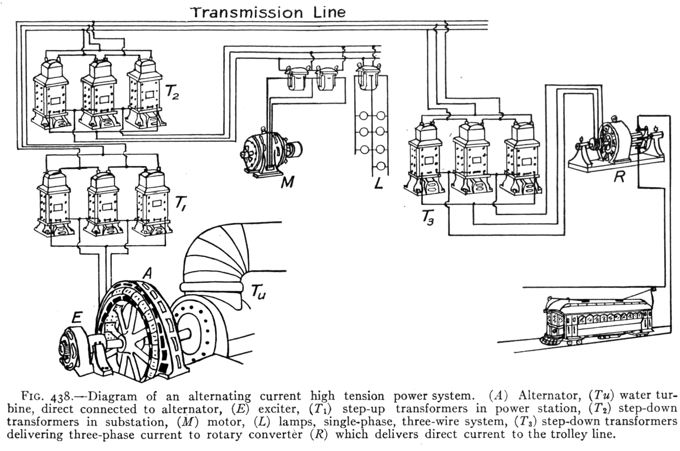
437. Transmission of Electric Power.?A field of peculiar usefulness for a.-c. currents is in the economical transmission of electric power. This fact is due to the following reasons: (a) The loss of electrical power in a transmission line is due to the production of heat; the heat produced being proportional to I2R, or to the square of the current intensity. Any lessening of the current flow required to transmit a given power will therefore increase the efficiency of transmission. (b) In order to employ a small current in transmitting a large amount of power, we must use a very high e.m.f. Such high electromotive forces, say from 60,000 to 100,000 volts, can be obtained only by the use of a.-c. transformers, since it is not practicable to build a direct current generator capable of producing 60,000 volts. In large power transmission systems, a.-c. generators are used to produce powerful alternating currents. The e.m.f. is then stepped up to a suitable voltage (2300-100,000) by transformers and sent over transmission lines to the various places where the power is to be used; at these places suitable transformers "step-down" the e.m.f. to a convenient or safe voltage for use. (See Fig. 442 of a transmission line and Fig. 438 of a large power transmission system, and Fig. 439 of an a.-c. generator and power plant.)
438. Power Factor.?The power factor is a matter of interest and importance in the use of a.-c. machines. Its meaning and use may be learned from the following explanation: In a direct current circuit, watts equals[Pg 477]
[Pg 478] volts times amperes. In an alternating current circuit, this equation is true only when the current is "in step" with the voltage, that is, only when there is no inductance or capacity in the circuit. If current and voltage are out of step, i.e., if there is lag or lead (see Fig. 434), the product of volts and amperes gives only the apparent power, the ratio between true and apparent power depending on the amount of lag or lead. This ratio is called the power factor. In an a.-c. circuit, then, the power equation is: watts = volts ? amperes ? power factor, or power factor = true power/apparent power. The product of volts and amperes is the apparent power and is called volt-amperes in distinction from the true power or watts. Therefore the following is true: power factor = true watts/volt-amperes.
 Fig. 439.?Power house showing alternators, direct connected to horizontal hydraulic turbines. Note the direct current "exciter" on end of shaft of alternator. (Courtesy of General Electric Co.)
[Pg 479]
Fig. 439.?Power house showing alternators, direct connected to horizontal hydraulic turbines. Note the direct current "exciter" on end of shaft of alternator. (Courtesy of General Electric Co.)
[Pg 479]
439. Single-phase Currents.?There are several kinds of a.-c. currents. One of the most common is the single-phase. It is simply the common a.-c. current used for light and power in the average home, and uses a two-wire circuit around which the current is rapidly alternating. Fig. 440 illustrates the changes of e.m.f. in an a.-c. single-phase current. It may be produced by a single coil rotating in a magnetic field. The curve of Fig. 440 represents one cycle, that is, one complete series of changes in the electromotive forces. At the end of the cycle the armature is in the same condition as at the beginning so far as the magnetic field is concerned. It then begins a new cycle. The ordinary commercial alternating current has a frequency of 60, that is 60 cycles per second. One rotation produces as many cycles as there are pairs of poles. For example, if there are 48 poles in the generator field, one rotation produces 24 cycles.
 Fig. 440.?Graph showing the e.m.f. changes of a single-phase current for one "cycle."
440. Three-phase Currents.?Now suppose we have three coils as in Fig. 441, the coils being evenly spaced, or 120 degrees apart, at A, B, and C. If the coils are rotated in a magnetic field, each will produce an electromotive[Pg 480] force. The result produced by three such coils is called a three-phase current. Ordinarily six wires, or three circuits, would be required to carry the current produced by three separate coils; for when coil "C" is in the 90 degree position, where its e.m.f. is a maximum, coil "B" is 120 degrees past its maximum, and coil "A" is 240 degrees past its maximum. The graph (Fig. 441) shows the maximum points of the three e.m.f's. separated by intervals of 120 degrees. In practice, however, it is found possible to use three wires instead of six, as explained in Art. 441.
Fig. 440.?Graph showing the e.m.f. changes of a single-phase current for one "cycle."
440. Three-phase Currents.?Now suppose we have three coils as in Fig. 441, the coils being evenly spaced, or 120 degrees apart, at A, B, and C. If the coils are rotated in a magnetic field, each will produce an electromotive[Pg 480] force. The result produced by three such coils is called a three-phase current. Ordinarily six wires, or three circuits, would be required to carry the current produced by three separate coils; for when coil "C" is in the 90 degree position, where its e.m.f. is a maximum, coil "B" is 120 degrees past its maximum, and coil "A" is 240 degrees past its maximum. The graph (Fig. 441) shows the maximum points of the three e.m.f's. separated by intervals of 120 degrees. In practice, however, it is found possible to use three wires instead of six, as explained in Art. 441.
 Fig. 441.?Graph showing the e.m.f. changes of a three-phase current for one "cycle."
441. Three-wire Transmission.?The currents produced in the three coils just described undergo precisely the same changes as those represented in the graph (Fig. 441) for the three electromotive forces. Careful examination of the graph will show that at any point the sum of the plus e.m.f's. equals the sum of the minus e.m.f's. In other words the algebraic sum of the three e.m.f's. is zero. Therefore if we properly connect a transmission line of three wires to the generator, the sum of the currents[Pg 481] leaving the generator will equal the sum of the currents returning to it. Since the algebraic sum of the currents produced by the three coil combination described in Art. 440 is always zero, it is possible to use three wires on three-phase transmission lines. Fig. 442 shows a "tower" carrying three, three-wire transmission lines. Long distance, high tension transmission lines are generally three-wire lines carrying three-phase a.-c. currents.
Fig. 441.?Graph showing the e.m.f. changes of a three-phase current for one "cycle."
441. Three-wire Transmission.?The currents produced in the three coils just described undergo precisely the same changes as those represented in the graph (Fig. 441) for the three electromotive forces. Careful examination of the graph will show that at any point the sum of the plus e.m.f's. equals the sum of the minus e.m.f's. In other words the algebraic sum of the three e.m.f's. is zero. Therefore if we properly connect a transmission line of three wires to the generator, the sum of the currents[Pg 481] leaving the generator will equal the sum of the currents returning to it. Since the algebraic sum of the currents produced by the three coil combination described in Art. 440 is always zero, it is possible to use three wires on three-phase transmission lines. Fig. 442 shows a "tower" carrying three, three-wire transmission lines. Long distance, high tension transmission lines are generally three-wire lines carrying three-phase a.-c. currents.
 Fig. 442.?A "tower" supporting three, three-phase circuits of a high tension transmission line.
442. Alternators.?A dynamo which delivers alternating current is known as an alternator. Commercial alternators have many pairs of poles in the field and as a rule the field rotates while the armature is stationary. The field must be supplied with direct current for the polarity of each coil in the field must remain unchanged. Usually[Pg 482] a separate "exciter" is used, which is a small direct current generator. The current from this exciter is fed into the rotating field by means of slip rings. Fig. 439 shows a d.-c. (direct current) exciter on the end of the armature shaft of the large alternator.
Fig. 442.?A "tower" supporting three, three-phase circuits of a high tension transmission line.
442. Alternators.?A dynamo which delivers alternating current is known as an alternator. Commercial alternators have many pairs of poles in the field and as a rule the field rotates while the armature is stationary. The field must be supplied with direct current for the polarity of each coil in the field must remain unchanged. Usually[Pg 482] a separate "exciter" is used, which is a small direct current generator. The current from this exciter is fed into the rotating field by means of slip rings. Fig. 439 shows a d.-c. (direct current) exciter on the end of the armature shaft of the large alternator.
 Fig. 443.?Diagram of a "Series Motor."
443. The A.-C. Series Motors.?The only type of motor that will run on either alternating or direct current is the series motor. The "universal" motor used in household appliances such as electric fans, vacuum cleaners, etc., is a series motor. The reason a series motor will run on either direct or alternating current is because the direction of rotation of the armature of a motor depends on (a) the direction of the current in the armature, and (b) the polarity of the field. Reversing either of these alone, reverses the direction of rotation of the armature, while reversing both at the same instant leaves the direction of rotation unchanged. Fig. 443 is a diagram of a series motor since the field coils and armature[Pg 483] are connected in series. On an a.-c. line, both field and armature current must therefore reverse at the same instant. In a shunt motor (similar to Fig. 286) we have a divided circuit, and the greater self-induction of the field coils causes an a.-c. current through these coils to lag behind that flowing in the armature so that the two currents do not reverse at the same instant.
Fig. 443.?Diagram of a "Series Motor."
443. The A.-C. Series Motors.?The only type of motor that will run on either alternating or direct current is the series motor. The "universal" motor used in household appliances such as electric fans, vacuum cleaners, etc., is a series motor. The reason a series motor will run on either direct or alternating current is because the direction of rotation of the armature of a motor depends on (a) the direction of the current in the armature, and (b) the polarity of the field. Reversing either of these alone, reverses the direction of rotation of the armature, while reversing both at the same instant leaves the direction of rotation unchanged. Fig. 443 is a diagram of a series motor since the field coils and armature[Pg 483] are connected in series. On an a.-c. line, both field and armature current must therefore reverse at the same instant. In a shunt motor (similar to Fig. 286) we have a divided circuit, and the greater self-induction of the field coils causes an a.-c. current through these coils to lag behind that flowing in the armature so that the two currents do not reverse at the same instant.
 Fig. 444.?Diagram of a gramme ring. It is shown connected to a single-phase current so as to produce a rotating magnetic field, similar to that obtained with a three-phase current. (Ahrens, Harley and Burns.)
 Fig. 445.?The "stator" of an induction motor.
444. The Induction Motor.?Another common type of a.-c. motor is the induction motor. Its advantage lies in its simplicity. It has neither commutator nor brushes, the armature having no connection with an external circuit. If the wires of a three-phase line be connected to a coil wound in the form of a gramme ring, the connections being 120 degrees apart as in Fig. 444, the magnetic field within this coil will change in the same manner as if a magnet were spinning upon a pivot at the center of the coil. Suppose the N pole at one instant is at A, in one-third of a cycle it moves to B, in another third to C, and in one cycle it makes a complete revolution. Thus we have a rotating magnetic field. If a cup of some non-magnetic metal such as aluminium or copper be placed on a pivot in the center of this coil, the cup is cut by the[Pg 484] moving lines of force and currents are induced in it. Because of these currents, the cup has a magnetic field of its own, and the action of the two magnetic fields is such as to pull the cup around and cause it to rotate in the same direction as that in which the field of the coil rotates. The coil represents the stationary part, the stator (Fig. 445) and the cup the rotating part, the rotor, of an induction motor. While the cup rotates in the same direction, it does not rotate so rapidly as the magnetic field. If it should it is plain that it would not cut the lines of force. The difference between the rate of rotation of the rotor and that of the magnetic field is called the "slip." The rotating part in small induction motors is frequently made in a single casting. In large motors, it is built up of heavy copper bars. Thus, from its appearance the common form[Pg 485] of rotor is known as the "squirrel cage" rotor. (See Fig. 446.)
Fig. 445.?The "stator" of an induction motor.
444. The Induction Motor.?Another common type of a.-c. motor is the induction motor. Its advantage lies in its simplicity. It has neither commutator nor brushes, the armature having no connection with an external circuit. If the wires of a three-phase line be connected to a coil wound in the form of a gramme ring, the connections being 120 degrees apart as in Fig. 444, the magnetic field within this coil will change in the same manner as if a magnet were spinning upon a pivot at the center of the coil. Suppose the N pole at one instant is at A, in one-third of a cycle it moves to B, in another third to C, and in one cycle it makes a complete revolution. Thus we have a rotating magnetic field. If a cup of some non-magnetic metal such as aluminium or copper be placed on a pivot in the center of this coil, the cup is cut by the[Pg 484] moving lines of force and currents are induced in it. Because of these currents, the cup has a magnetic field of its own, and the action of the two magnetic fields is such as to pull the cup around and cause it to rotate in the same direction as that in which the field of the coil rotates. The coil represents the stationary part, the stator (Fig. 445) and the cup the rotating part, the rotor, of an induction motor. While the cup rotates in the same direction, it does not rotate so rapidly as the magnetic field. If it should it is plain that it would not cut the lines of force. The difference between the rate of rotation of the rotor and that of the magnetic field is called the "slip." The rotating part in small induction motors is frequently made in a single casting. In large motors, it is built up of heavy copper bars. Thus, from its appearance the common form[Pg 485] of rotor is known as the "squirrel cage" rotor. (See Fig. 446.)
 Fig. 446.?The "rotor" of an induction motor.
 Fig. 447.?Diagram illustrating the principle of the synchronous motor. The armature coil passes the position shown in the figure at the instant the current in the line reverses. Thus the armature keeps with the line current, making one revolution with each "cycle."
445. A synchronous motor is one that keeps step with the alterations of an alternating current. The line current is fed into the armature by means of two slip rings and brushes. The principle of the synchronous motor is illustrated in Fig. 447. This shows a motor having a two-pole field. The armature current must be reversed[Pg 486] twice in each revolution. The reversal must take place when the armature winding is perpendicular to the lines of force of the field. In a direct current motor this reversal is brought about by the commutator. In a synchronous motor the armature reaches the 90 degree position at the exact instant at which the current reverses in the line. Thus in the case of a two-pole motor the armature must make exactly one revolution for each cycle; it is, therefore, a constant speed motor. Such motors are frequently employed in converter stations where alternating current is converted into direct current by what are called rotary converters.
Fig. 447.?Diagram illustrating the principle of the synchronous motor. The armature coil passes the position shown in the figure at the instant the current in the line reverses. Thus the armature keeps with the line current, making one revolution with each "cycle."
445. A synchronous motor is one that keeps step with the alterations of an alternating current. The line current is fed into the armature by means of two slip rings and brushes. The principle of the synchronous motor is illustrated in Fig. 447. This shows a motor having a two-pole field. The armature current must be reversed[Pg 486] twice in each revolution. The reversal must take place when the armature winding is perpendicular to the lines of force of the field. In a direct current motor this reversal is brought about by the commutator. In a synchronous motor the armature reaches the 90 degree position at the exact instant at which the current reverses in the line. Thus in the case of a two-pole motor the armature must make exactly one revolution for each cycle; it is, therefore, a constant speed motor. Such motors are frequently employed in converter stations where alternating current is converted into direct current by what are called rotary converters.
In practice the synchronous motor has a number of pairs of field poles. It is essentially an alternating current generator running as a motor. One of the principal uses of the synchronous motor is that of a converter, receiving alternating current and delivering direct current. Synchronous motors are also used in transmission lines to aid in maintaining constant voltage.
Alternating currents, alternating fields.
Transformers, voltage relation of coils, power and core losses.
Self-induction, inductance, and coke coils, uses, applications.
Impedance, reactance, and resistance; relation and effects.
Condensers, uses and applications with a-c. circuits.
Alternating current power transmission; uses, advantages.
Power factor, lag, lead, volt-amperes, true watts.
Single- and three-phase currents; uses and nature of each.
Three-wire transmission systems, alternators, construction, and action.
A-c. motors, series, induction, synchronous.
WIRELESS TELEPHONY AND ALTERNATING CURRENTS
The developments in wireless communication have been so rapid during recent years that a more extended account, than that given in Art. 417 of the apparatus and methods used at the present time, seems desirable. The study of Alternating Currents is also included with the idea that it will make the text more complete and of wider usefulness.
Wireless Telephony
425. The Wireless Telephone.?One of the most important developments in wireless communication in recent years has been in wireless telephony. We realize its possibilities, when we hear of the achievements of talking across an ocean or between airplanes and the ground.The wireless telephone can be best understood by comparing it with the common telephone. When the latter is in use, a direct current flows continually through the instrument. (See Arts. 312-316.) When a person speaks into the transmitter, the sound waves of the voice cause the diaphragm to vibrate, this action causes rapid changes in the resistance of the transmitter, which in turn causes the direct current to fluctuate just in step with the pulses of the voice waves. This fluctuating direct current passes through the primary of an induction coil, producing in the secondary an intensified alternating current. This passes over the line wires to the receiver where it produces[Pg 461] variations in the magnetic field affecting the receiver diaphragm, causing the latter to reproduce the voice of the person speaking in the transmitter. Now to make the comparison clear, two facts must be noted with regard to the wire telephone: first, there must be an action in the transmitter which causes variations in a current through the instrument; second, this fluctuating current produces a more intense alternating current which flows over the line and affects the receiver diaphragm, producing there sound vibrations of greater intensity than those used at the transmitter. This added energy comes from the current flowing through the transmitter. The case is analogous to that of an electric bell. The armature of the bell vibrates with greater energy than is required to push the button, the extra energy being derived from the battery.
426. The Action of the Wireless Telephone.?In the wireless telephone we have a continuous stream of electric waves of high frequency. (See Fig. 425A.) This stream of electric waves corresponds to the current that flows through the transmitter in the wire telephone. These waves are of such high frequency that even though we had a receiver diaphragm vibrating in step with the waves, we could not hear the sound because the human ear cannot hear a sound which consists of more than about 40,000 vibrations per second. The sound waves act upon this stream of waves very much, as in the wire telephone, the transmitter acts to modify the line current. The impulses caused by the voice are much slower than the electric waves first mentioned and these slower impulses are reproduced in the receiver. Not only are these slower impulses reproduced but they are amplified, that is, produced with greater energy than the impulses impressed on the stream of waves. Fig.[Pg 462] 425A represents as nearly as is possible in a diagram the continuous stream of electric waves. Fig. 426B, represents the impulses produced by the sound alone, and Fig.[Pg 463] 426C, shows how these voice impulses are impressed on the stream of waves.
Fig. 425.?A, unmodified high frequency waves; B, waves of voice frequency; C, high frequency waves modified by waves of voice frequency. Fig. 426.?Vacuum tube, transmitting type. (Western Electric Co.)Fig. 427.?Vacuum tube, receiving type. (Western Electric Co.)
Fig. 428.?Diagram of wireless telephone transmitting set. Fig. 429.?View of wireless telephone set. [Pg 466]
Alternating Currents
428. Alternating currents are of interest to us because of their general commercial use. To understand the reason for the extensive application of alternating currents it is necessary to learn the fundamental principles which pertain to them. The production of such currents has already been explained in Arts. 300-304. It should be remembered that the current developed in the armature of a dynamo is alternating. A dynamo may deliver a direct or an alternating current, depending on the method of collecting the current from the armature. If a commutator is used, the machine delivers direct current, if slip rings are employed, an alternating current is delivered.429. The Magnetic Field of an Alternating Current.?The magnetic field of a direct current has been considered in Arts. 255-256. It has been shown to be arranged in circles about the conductor, according to the Right Hand Rule. (See Figs. 229 and 230.) These facts will help one to understand the following experiment:
If a number of magnetic compasses be arranged in a circle about a straight vertical wire carrying a direct current, the compass needles will point out a circle about the wire. (See Fig. 430, A.) If now the current be reversed the compass needles will reverse themselves and point in a direction just opposite to that taken at first. (See Fig. 430, B.) This will be clear if you imagine yourself walking around the wire in the direction the compass needles pointed at first, and then walking around the wire in the reverse direction. This illustrates what happens in the field of an alternating current. The field reverses each time the current reverses.
The magnetic field of an alternating current not only rapidly reverses itself, but also continually changes in intensity. At the instant when the current reverses, the force of the magnetic field is zero since the current at that instant is zero. As the current begins flowing and increases[Pg 467] to its maximum intensity, the magnetic field appears and increases in intensity; and as the current decreases to zero, the magnetic field changes in a similar manner. The field as it grows in strength extends farther and farther from the wire, as it decreases in strength it contracts or draws closer to the wire. Thus the magnetic field may be said to expand and contract. We may picture the lines of force as continually moving. In a typical a.-c. circuit, the complete series of changes takes place in a small fraction of a second, and is repeated many times over in a second. Contrast this with the magnetic field of a constant direct current. Here the magnetic field has the same direction as long as the current flows and does not change in strength. This comparison is important because most of the differences between direct and alternating currents depend on differences in the action of their magnetic fields. Fig. 430.?Arrangement of compasses about a wire carrying an alternating current.
A coil having several hundred turns of No. 18 d.c.c. copper wire is placed over one arm of a "U" shaped iron core (see Fig. 431) and then[Pg 468] connected to a 110 volt a.-c. lighting circuit. Another coil (S) having about 50 turns of No. 22 d.c.c. copper wire is connected to an electric bell or buzzer, or a low voltage electric light bulb. When the small coil is held over the other arm of the "U" shaped iron core, the bell rings or the bulb glows. It is evident that the electromotive force developed in the small coil (S) is due to the alternating magnetic field surging back and forth through the iron core. In Fig. 431 the core is "open" since the magnetic field must pass through the air from one end of the core to the other. A typical transformer has a closed core to provide a closed magnetic circuit. To secure this, take a suitable bar of iron and lay across the end of the "U" shaped core, and notice any change in the induced current produced in the small coil, due to increased movement of magnetism through the closed iron core.
Fig. 431.?Diagram of a transformer. 431. Voltage Relation in a Transformer.?In the experiment described above, a bell was rung by an induced current produced in the secondary coil. The induced e.m.f. was less than the voltage of the primary coil partly because there was some magnetic leakage, but mainly[Pg 469] because there were fewer turns of wire on the secondary. In a commercial transformer the magnetic leakage is practically zero. In such a case, the ratio of the number of turns on the primary coil to the number on the secondary equals the ratio of the e.m.f. induced in the primary to the e.m.f. induced in the secondary. Suppose, for example, we wish to make a bell ringing transformer to use on a 110 volt lighting circuit, 10 volts being required for the bell; the secondary will then need one-eleventh of the number of turns of the primary. So that if 550 turns are on the primary, then 50 turns will be needed for the secondary. This will be a "step-down" transformer. On the other hand, suppose we wish to "step-up" the voltage as is done in a certain power station where the voltage of the generators is 6000 volts, the voltage being stepped up to 44,000 by means of large transformers. This means that the secondary coils have approximately 7-1/3 times as many turns as the primary.
432. Power Loss in a Transformer.?When the voltage is "stepped up" in a transformer, do we gain power? To answer this question we must remember that electric power does not depend on voltage alone but on the product of e.m.f. and current intensity. (See Art. 291.) By tests with a.-c. voltmeters and ammeters, we find that when the secondary e.m.f. is greater than the primary e.m.f., the secondary current intensity is less than that in the primary. It is also found that the power developed is less than the power received by the transformer, i.e., the "output" is less than the "input" as we would expect from the law of machines. The power loss is mainly due to the work required to reverse the magnetism, that is, to continually reverse the position of the iron molecules. (See Art. 205.) The energy lost in this manner is known as "core loss" since it occurs in the[Pg 470] iron core. The lost energy appears as heat. So much heat is developed in large transformers that special means of cooling are provided. In order to make the heat developed as small as possible, the cores are "laminated" (see Fig. 305, p. 346), that is, built up of thin sheets of iron, because if the iron cores were solid, the changing magnetic fields would induce electric currents in the iron cores, which would produce an excessive amount of heat with a correspondingly large power loss.
Fig. 432.?Diagram of "bell-ringing" transformer. Fig. 433.?A circuit containing a choke coil. Fig. 434.?Diagram showing graphically an alternating current with a "lag" of 30? behind its electromotive force. 434. Reactance and Impedance.?A choke coil has resistance as well as inductance. Its resistance can be found by the voltmeter-ammeter method, using a direct current. (See Art. 278.) Let us take for example the primary winding of a bell ringing transformer. Using a direct current and testing the coil with a voltmeter and ammeter we find its resistance to be, let us say, one ohm. If we connect the same coil across a 110 volt a.-c. line we find the current[Pg 473] to be very small, say 0.05 ampere. The coil now has resistance and reactance. Reactance is the effect of self-induction in hindering the flow of current. It is measured in ohms. The combined effect of resistance and reactance is called impedance. In the example above, the coil has 110 (volts)/0.05 (ampere) = 2200 ohms of impedance. In applying Ohm's law to an alternating current circuit, impedance must be substituted for resistance. Ohm's law as applied to an a-c. circuit should be stated: "Current intensity equals e.m.f. divided by impedance", or I = E/Z. (Z = impedance.)
Fig. 435.?The relation between resistance, reactance and impedance. Exercises
1. Find the reactance of a choke coil having a resistance of 10 ohms, when its impedance is 50 ohms. How great a current flows through this coil if the terminal voltage is 110 volts?2. When the bell is ringing, the primary of a bell ringing transformer has an appreciable current. Suppose this current is 0.2 ampere. What is the impedance if the voltage of the line is 115 volts? What is the reactance if the resistance is 1 ohm?
3. The primary of a large transformer has a terminal voltage of 6000 volts and a current of 600 amperes. What is the impedance? If the resistance is 6 ohms, what is the reactance?
Fig. 436.?A telephone set showing a condenser used in the circuit of the "ringer." 436. The action of a condenser in an alternating current circuit may be illustrated by the following experiment. Connect twelve, 1 m.f. (microfarad) condensers, in parallel, and then attach them to a 110 volt a.-c. line so that an[Pg 475] incandescent lamp is in circuit as shown in Fig. 437. The lamp will be found to glow brightly, although there is no electrical connection between the two sets of condenser plates. If the same arrangement is connected to a 110 volt direct current circuit, the lamp does not glow because it is really an open circuit. The lamp glows on an a.-c. circuit because, although no electricity flows through the condenser, it does flow into and out of the condenser, surging back and forth through the lamp with sufficient intensity to cause it to glow brightly. When the a.-c. current moves one way in the circuit, one set of plates of the condensers becomes charged positively, the other, negatively. When the a.-c. current reverses, the charges on the condenser plates reverse. In the ordinary lighting circuit 120 reversals take place each second, so that electricity rapidly flows into and out of the condensers. On removing one condenser after another from the circuit, the lamp is found to glow less and less, till when but one condenser is left, no glowing is observed, since one small condenser does not have sufficient capacity.
Fig. 437.?Twelve condensers in circuit with an incandescent lamp. [Pg 476]
A condenser, on account of its capacity, causes an a.-c. current to lead the voltage, that is the current reaches its maximum value before the voltage does. In this respect a condenser has an effect opposite to that of the self-induction of a choke coil (the latter causing the current to "lag"). (See Fig. 435.)
437. Transmission of Electric Power.?A field of peculiar usefulness for a.-c. currents is in the economical transmission of electric power. This fact is due to the following reasons: (a) The loss of electrical power in a transmission line is due to the production of heat; the heat produced being proportional to I2R, or to the square of the current intensity. Any lessening of the current flow required to transmit a given power will therefore increase the efficiency of transmission. (b) In order to employ a small current in transmitting a large amount of power, we must use a very high e.m.f. Such high electromotive forces, say from 60,000 to 100,000 volts, can be obtained only by the use of a.-c. transformers, since it is not practicable to build a direct current generator capable of producing 60,000 volts. In large power transmission systems, a.-c. generators are used to produce powerful alternating currents. The e.m.f. is then stepped up to a suitable voltage (2300-100,000) by transformers and sent over transmission lines to the various places where the power is to be used; at these places suitable transformers "step-down" the e.m.f. to a convenient or safe voltage for use. (See Fig. 442 of a transmission line and Fig. 438 of a large power transmission system, and Fig. 439 of an a.-c. generator and power plant.)
438. Power Factor.?The power factor is a matter of interest and importance in the use of a.-c. machines. Its meaning and use may be learned from the following explanation: In a direct current circuit, watts equals[Pg 477]
[Pg 478] volts times amperes. In an alternating current circuit, this equation is true only when the current is "in step" with the voltage, that is, only when there is no inductance or capacity in the circuit. If current and voltage are out of step, i.e., if there is lag or lead (see Fig. 434), the product of volts and amperes gives only the apparent power, the ratio between true and apparent power depending on the amount of lag or lead. This ratio is called the power factor. In an a.-c. circuit, then, the power equation is: watts = volts ? amperes ? power factor, or power factor = true power/apparent power. The product of volts and amperes is the apparent power and is called volt-amperes in distinction from the true power or watts. Therefore the following is true: power factor = true watts/volt-amperes.
Fig. 439.?Power house showing alternators, direct connected to horizontal hydraulic turbines. Note the direct current "exciter" on end of shaft of alternator. (Courtesy of General Electric Co.) 439. Single-phase Currents.?There are several kinds of a.-c. currents. One of the most common is the single-phase. It is simply the common a.-c. current used for light and power in the average home, and uses a two-wire circuit around which the current is rapidly alternating. Fig. 440 illustrates the changes of e.m.f. in an a.-c. single-phase current. It may be produced by a single coil rotating in a magnetic field. The curve of Fig. 440 represents one cycle, that is, one complete series of changes in the electromotive forces. At the end of the cycle the armature is in the same condition as at the beginning so far as the magnetic field is concerned. It then begins a new cycle. The ordinary commercial alternating current has a frequency of 60, that is 60 cycles per second. One rotation produces as many cycles as there are pairs of poles. For example, if there are 48 poles in the generator field, one rotation produces 24 cycles.
Fig. 440.?Graph showing the e.m.f. changes of a single-phase current for one "cycle." Fig. 441.?Graph showing the e.m.f. changes of a three-phase current for one "cycle." Fig. 442.?A "tower" supporting three, three-phase circuits of a high tension transmission line. Fig. 443.?Diagram of a "Series Motor." Fig. 444.?Diagram of a gramme ring. It is shown connected to a single-phase current so as to produce a rotating magnetic field, similar to that obtained with a three-phase current. (Ahrens, Harley and Burns.) Fig. 445.?The "stator" of an induction motor. Fig. 446.?The "rotor" of an induction motor. Fig. 447.?Diagram illustrating the principle of the synchronous motor. The armature coil passes the position shown in the figure at the instant the current in the line reverses. Thus the armature keeps with the line current, making one revolution with each "cycle." In practice the synchronous motor has a number of pairs of field poles. It is essentially an alternating current generator running as a motor. One of the principal uses of the synchronous motor is that of a converter, receiving alternating current and delivering direct current. Synchronous motors are also used in transmission lines to aid in maintaining constant voltage.
Important Topics
The wireless telephone, essential parts, action, arrangement.Alternating currents, alternating fields.
Transformers, voltage relation of coils, power and core losses.
Self-induction, inductance, and coke coils, uses, applications.
Impedance, reactance, and resistance; relation and effects.
Condensers, uses and applications with a-c. circuits.
Alternating current power transmission; uses, advantages.
Power factor, lag, lead, volt-amperes, true watts.
Single- and three-phase currents; uses and nature of each.
Three-wire transmission systems, alternators, construction, and action.
A-c. motors, series, induction, synchronous.
Commentaires
Enregistrer un commentaire