EVERY animal is a complex machine, provided with
its own motive power and a brain for directing the operation of its own
mechanical elements. Not satisfied with the mechanism that nature has
put into the human machine, man has reached for other elements and
devised mechanisms of his own in order to supplement the human machine
and increase its efficiency. At first, as we have seen, these elements
were hand tools of the crudest sort; but they were gradually improved
and then they were combined into what we term machines. In developing
these machines, he naturally took his own system as a pattern and was
guided to a large extent by an examination of his own physical
structure. We see this very clearly in the names of the different parts
of machinery, which are taken from the names of similar parts in the
human frame. Almost every member of the body is used in mechanical
terminology. For instance, we have the “head” and the “foot,” the “arms”
and the “legs,” the “fingers” and the “ankles,” “elbows,” “shoulders,”
“trunk,” “hips,” and various parts of the face, such as the “eyes,”
“ears,” “nose,” “mouth,” “teeth,” “lips,” and even the “gums,” to
indicate parts of machinery which have some remote resemblance to these
features.
Before we can understand machinery we must have some general knowledge of the elements of
which it is composed. Probably most of the readers of this book already
possess a fair knowledge of machine elements and mechanical movements
and they can well afford to skip this chapter. However, for the benefit
of the uninitiated, we must put a machine on the operating table,
dissect it, and explain its anatomical structure. We cannot attempt a
very detailed study, but will confine ourselves to the most important
elements.
Every machine is made up of movable parts and fixed parts, the
latter serving to guide or constrain the motion of the former; for no
combination of elements will constitute a machine unless the parts are
constrained to move in certain predetermined directions.
THE LEVER
Among the moving elements the first to be considered is the
lever, which really forms a broad classification comprising many
elements that will hardly be recognized as levers at first blush. Levers
in some form are to be found in practically every machine. A wheel, a
gear, and a pulley are really levers in disguise, as will be explained
presently.
Of course everyone knows that a simple lever consists of a rigid
bar that swings on a fulcrum. The fulcrum may be a knife edge, a shaft
passing through the bar or any element on which the bar can be swung or
oscillated. The purpose of the lever is to give a certain advantage in
the application of a force to a load. This may be a change of speed and
distance of travel, and hence of power, or merely a change of direction.

FIG. 1.—THREE ORDERS OF SIMPLE LEVERS
There are three types or
orders of levers produced by
varying the relative positions of the points where the fulcrum, the
force or effort, and the weight or load are applied. These are shown in
Figure 1. In the lever of the
first order the fulcrum is placed between the effort and the weight; in the lever of the
second order the weight is applied between the fulcrum and the effort; and in the lever of the
third order
the effort is applied between the fulcrum and the weight. In each case
that part of the lever which extends from the fulcrum to the point where
the effort is applied is called the
effort arm, and that which extends from the fulcrum to the point where the weight is supported is the
weight arm.
The weight that can be lifted with a given effort depends upon the
ratio of the effort arm to the weight arm. If the two arms are of equal
length, the effort is equal to the weight, but twice the weight can be
lifted with the same effort if the effort arm is twice as long as the
weight arm. You can lift a ton with an effort of only 100 pounds if your effort arm is twenty times as long
as your weight arm but the end of your effort arm would have to move
twenty inches to raise the ton weight one inch. We are assuming in all
these cases that the lever itself has no weight and that there is no
friction at the fulcrum.
Of course levers are not used merely for the purpose of lifting
weight, but to overcome any resistance or merely to apply pressure upon
an object. In almost every household we may find examples of the three
orders of levers. A pair of shears, for instance, is composed of two
levers of the first order, swinging on a common fulcrum. The effort is
applied at the handles, and the weight or load is the material that is
cut by the blades or, speaking more technically, the handles are the
effort arms and the blades are the
weight arms.
A material that is too tough to be cut at the tip ends of the blades
may be easily cut if we move it in near the fulcrum or pin that hinges
the blades together; for by doing this we shorten the weight arms,
because the weight arm is measured not to the end of the blade, but to
the point where it is cutting into the material. To cut very tough
material, such as heavy tin or sheet steel, we use long-handled
short-bladed shears. The cutting pressure depends upon the ratio of the
effort arm to the weight arm. If the effort arms are twice as long as
the weight arms, the cutting pressure is twice as great as that applied
at the handles.
A nutcracker consists of a pair of levers of the second order.
The fulcrum is at one end and the effort or pressure is applied at the
opposite end of the levers or handles, while the equivalent of the
weight (in this case the nut) is placed between the effort and the
fulcrum. Again the
effort arm is
[24]
measured from the fulcrum or hinge pin of the tool to the point where
the hand pressure is applied, and the weight arm is measured from the
fulcrum to the nut. The effort arm may be four or five times as long as
the weight arm, so that the pressure exerted on the nut is four or five
times as great as that exerted by the hand on the ends of the handles.

FIG. 2.—AN ANGULAR OR BELL-CRANK LEVER
In the case of a pair of sugar tongs we have another tool
something like the nutcracker in construction, but here the weight,
i.e., the lump of sugar, is seized by the ends of the tongs while the
hand pressure is applied somewhere between the fulcrum and the weight.
Hence we have here a lever or pair of levers of the third order. The
effort arm of a pair of tongs is always shorter than the
weight arm
and the pressure on the sugar lump is always less than that exerted on
the tongs by the hand. Evidently the most powerful tool of the three is
the nutcracker, because the effort arms extend over the full length of
the tool and are always longer than the weight arms.
A lever need not consist of a straight bar; the effort arm may
form an angle with the weight arm, forming what is known as an angular
or bell-crank
lever (Figure 2). When a common claw hammer is used to pull out a nail,
the claws that slip under the head of the nail form the weight arm and
the hammer handle the effort arm. A horizontal pull on the handle
produces a vertical lift on the nail.
Sometimes two or more levers are interconnected, as in Figure 3,
the effort arm of one being linked to the weight arm of the other. This
serves to increase the lifting force at the weight and at the same time
keep the mechanism within compact limits. Such compounding can go on
indefinitely and is subject to all sorts of variations.

FIG. 3.—COMPOUND LEVERAGE
One thing we must not forget, and it is a matter that is commonly
overlooked by perpetual motion cranks, namely, that while a pound of
pressure on the effort arm may be made to lift two, four, or a hundred
times as many pounds on the weight arm by varying the relative length of
these arms, it has to move two, four, or a hundred times as far as the
weight arm, so that the work done on one side of the fulcrum is always
exactly equal to that done on the other side.
CONTINUOUS REVOLVING LEVERAGE

FIG. 4.—PRIMITIVE GEAR WHEELS—TWO COACTING GROUPS OF LEVERS
If we take a number of levers radiating from a common fulcrum
like the spokes of a carriage wheel, we have a primitive gear wheel. Two
such groups of levers may be mounted on parallel shafts so that when
one is turned its spokes will successively engage the spokes of the
other group and make the latter turn (see Figure 4). Each spoke is first
an effort arm on one side of the wheel and then a weight arm as it
turns around to the other side of the wheel, and as the effort arms and
weight arms are of the same length there is no multiplication of power. A
pound on one side of the wheel cannot lift more than a pound on the
other. The driven wheel receives the same power as the driving wheel
except for such loss as may be due to friction at the bearings or where
the spokes contact. The only advantage of such a pair of gears is that
the direction of rotation of the driven wheel is the reverse of that of
the driving wheel. If the spokes of one wheel are longer than those of
the other, we have at once a variation in the rate of rotation
proportional to the relative diameters of the two wheels. In Figure 5,
for instance, the diameter of the driving wheel A is twice the diameter of the driven
gear B, and so, for each revolution of A, B must make two revolutions,
i.e., the driver must make two revolutions for each revolution of the
driven wheel. In other words, the speed of revolution is doubled.
However, if we make B the driver the speed of the driven wheel A will be
half of that of wheel B.

FIG. 5.—COACTING LEVERS OF UNEQUAL LENGTH
In primitive machines spoke gears were seldom mounted
on parallel shafts because of the difficulty of keeping the spokes in
alignment. Instead, one shaft was mounted at right angles to the other
so that one set of spokes would cross the other (Figure 6), thus
producing the equivalent of a bevel gear. This was of advantage in
changing the plane of rotation. A later development was the barrel or lantern gear,
which permitted transfer of power without changing the plane of
rotation. A cylindrical bundle of rods constituted one of the wheels (as
shown in Figure 7). Instead of being crudely formed of spokes, the
other wheel sometimes consisted of a
disk with pins radiating from its rim. Such gears in far more refined
form are still used in modern clocks and watches. A still further
development for transmitting motion to a plane at right angles to that
of the driving shaft is shown in Figure 8. Here we have a crown gear in which the pins instead of radiating from the periphery of the disk project from the side face of the gear.

FIG. 6.—PRIMITIVE EQUIVALENT OF THE BEVEL GEAR

FIG. 7.—PRIMITIVE LANTERN GEAR
Turning back to our first spoked wheels, it is very evident that
we may put a rim over the spokes or even fill in between the spokes and
convert the wheels into solid disks that are in frictional engagement
with each other without getting away from the fact that we are dealing
with levers. Each wheel, then, consists of a continuous revolving lever.
Friction gears are used quite commonly in machinery when it is
desirable to have the wheels slip if subjected to excessive strain.
TOOTHED GEARS
By forming teeth on one gear to mesh between similar teeth on the
other, we convert the friction gears into a pair of spur gears (Figure
9). We need not go into the intricacies of the form of gear teeth. They
are designed to be in continuous rolling contact while they are in mesh.
The novice is apt to call all spur gears “cogwheels” and gear-teeth
“cogs.” Mechanics, however, recognize a difference between cog wheels
and spur wheels. In the former, the teeth, or cogs, are not cast upon or
cut out of the wheel body, but are separate pieces fitted to the wheel.
Such wheels are found in old water mills. They consist of wooden wheels
with iron or steel teeth mortised in the wooden rim of the wheel. In
general it is safer to speak of spur gears because there are few
cogwheels now in use.

FIG. 8.—CROWN AND LANTERN GEAR
When a small gear engages a large one, the former is commonly known as a
pinion.

FIG. 9.—SPUR AND PINION GEAR

FIG. 10.—BEVEL FRICTION GEARS
If two friction wheels are to turn at right angles one to the
other, they must have conical bearing surfaces, as in Figure 10. The
angle between the shafts of the two gears and the relative size of the
gears may be changed as desired, provided each cone surface has its apex
at the intersection of the two shafts or axes. It is easy to understand
how such conical friction gears may be converted into toothed bevel
gears (Figure 11), by forming teeth on the conical
surfaces, and it will be evident that the teeth must taper toward the
apex of the two cones. Two bevel gears of equal diameter, and with
shafts set at right angles one to the other, are known as
miter gears.

FIG. 11.—TOOTHED BEVEL GEARS
So far we have not shown any combination of gearing that will
multiply power. In Figure 5, the driver A is twice the diameter of the
driven wheel B, and the latter makes two revolutions for one of A, but
the speed at the periphery of the two wheels is the same. A pull of one
pound at the point
a produces a pressure of one pound at
b, and this in turn produces a lift of one pound at
c
because the levers in each wheel are perfectly balanced, that is, each
lever has equal effort and weight arms. The way to obtain an increase of
power and of peripheral speed is to fasten two wheels of unequal
diameters together on the same center and apply the effort to one of the
wheels (as in Figure 12) and the weight to the other wheel. This gives
us what is technically known as a
wheel and axle. The dotted
lines show that we have here a lever of the first order which can be
used to multiply power in the same way that a bar lever does. If one
wheel is twice the diameter of the other then a pound of effort will lift two pounds of weight.

FIG. 12.—WHEEL AND AXLE OR REVOLVING LEVER OF FIRST ORDER

FIG. 13.—REVOLVING LEVERS OF THE 2D AND 3D ORDER
Figure 13 shows how the effort and weight can be shifted about in
such fashion as to give us a lever of the second and one of the third
order. The power may be enormously increased and the speed of the final
wheel greatly reduced by setting up a train of gears in which the effort
is received by the larger one of each couple and is delivered by the
smaller one. In Figure 14 the smaller wheels are half the diameter of
the larger ones. A pound of pressure at A will amount to 2 at B, 4 at C,
8 at D, 16 at E, and 32 at F. On the other hand, point A will have to
move through 32 inches to make the point F move an inch.

RAISING WATER WITH A CHAIN OF POTS
A primitive pump still used in Egypt

A HORSE-OPERATED CHAIN-PUMP USED IN GREECE

MULTIPLE SPINDLE DRILL IN MOTOR CAR FACTORY

FIG. 14.—A TRAIN OF SPUR GEARS

FIG. 15.—PULLEYS OF THE 1ST, 2D, AND 3D ORDERS

FIG. 16.—TYPICAL ARRANGEMENT OF BLOCK AND TACKLE
A pulley is merely a modification of the wheel. Figure 15 shows
how it may be arranged to correspond to the three orders of simple
levers. If the pulley axis is fixed, as in the first order, the effort
and weight arms are equal and hence balanced. In the second order the
wheel is bodily movable, hence one pound will raise two pounds of weight
because the power arm is twice as long as the weight arm, while in the
third order it takes two pounds of lift to raise one pound of weight.
There is no end of possible combinations of pulleys which will multiply
power in the same way that bar levers do when compounded. A common
arrangement of block and tackle is given in Figure 16. There is a
four-sheave pulley block above and a three-sheave block below, but in
order to trace the rope clearly the pulley wheels or sheaves are
represented as of different diameters. The arrangement consists of a
series of levers of the first order in the upper pulley block coupled to
a series of levers of the second order in the lower block. To find the
weight that a given
power will lift, multiply the effort by the number of strands of rope
that are supporting the weight. In this case there are seven such
strands, not counting the strand E, to which the effort or pull is
applied. This means that a pull of a hundred pounds at E will lift 700
pounds at W. Of course a pull of seven feet at E will raise the weight
only one foot.

FIG. 17.—INCLINED PLANE WITH EFFORT PARALLEL TO THE INCLINED FACE
THE INCLINED PLANE AND ITS FAMILY
The inclined plane constitutes a second broad classification of
machine elements. The wedge, the screw, the cam, and the eccentric, all
belong to the family of the inclined plane.

FIG. 18.—INCLINED PLANE WITH EFFORT PARALLEL TO THE BASE
A simple form of inclined plane is pictured in Figure 17, which
shows a weight W being rolled up an incline. The effort required to
carry it to the top of the incline depends, of course, upon the
steepness of the incline. The drawing shows a rise of 3 feet on a slope 5
feet long, and the weight of the wheel is, say 20 pounds. To find the
effort required, the weight is multiplied by the rise (20 × 3 = 60) and
divided by the length of the slope (60/5 = 12) and we find that it takes
only 12 pounds to roll the 20-pound wheel to the top of the incline.
This holds true when the pull is parallel to the inclined face. If the
pull is parallel to the base of the incline, as in Figure 18, we must
divide by the length of the base instead of the length of the incline
(60/4 = 15) and we find that it takes 15 pounds of effort to pull the
weight up the incline. If the pull is exerted at an angle both to the
base and the inclined face, we have a problem that is slightly more
complicated and we need not go into it here because it involves a bit of
trigonometry. In all cases, however, it may be noted that the amount of
rope that is taken in, in hauling the weight up the incline, bears a
definite relation to the amount of effort required to raise the weight.
In Figure 17, 5 feet of rope must be pulled in, in order to raise the
weight 3 feet, so that ⅗ of 20 or 12 pounds is all that is required to
pull up the weight, while in Figure 18, 4 feet of rope is hauled in for a
lift of 3 feet, so that ¾ of 20 or 15 pounds is required to pull up the
weight. In this
respect the inclined plane is exactly like the lever or the pulley, for the
effort multiplied by the
distance through which it is exerted is always exactly equal to the
weight multiplied by the
distance
through which it moves. Thus in Figure 17, the effort 12 pounds
multiplied by the distance 5 = the weight 20 pounds times the distance
3, and in Figure 18, effort 15 x distance 4 = weight 20 x distance 3. Of
course, we are ignoring the weight of the rope and the friction which,
in actual practice, are important factors to be reckoned with.
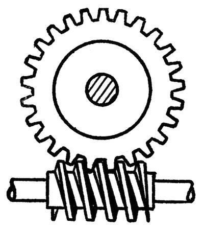
FIG. 19.—ENDLESS SCREW OR WORM GEAR
So far we have considered a fixed inclined plane, but when the
inclined plane is moved between the weight and a fixed base it is known
as a wedge, and in this case, too, the effort required to move the wedge
multiplied by the distance the wedge moves is equal to the weight
multiplied by the distance it is lifted.
The commonest form of
inclined plane is the screw which is merely an inclined plane bent
around a cylinder. A screw engaging a toothed wheel, as in Figure 19,
gives a
combination known as an “endless screw,” or, more commonly, as a worm
gear. The screw or worm is always the driver, and as it must make a
complete turn to move the gear through a space of one tooth, the power
of this combination is very great. It is practically impossible to turn
the worm by using the gear wheel as a driver because the friction
developed at the point where the worm and gear contact is very great.
For this reason worm gearing is used in the steering gear of
automobiles. The shaft of the steering wheel is fitted with a worm which
meshes with a worm gear on the parts connected with the wheels. It is
very easy to turn the wheels by operating the steering wheel, but if the
wheels strike a rut or a stone they are not deflected from their
course, because the worm makes it impossible for them to turn the
steering wheel.

FIG. 20.—HELICAL OR SPIRAL GEARS
The spiral gear shown in Figure 20 is a cross between a worm gear and spur gear. The teeth are
spirals set at an angle of 45 degrees to the axis of the wheel. In this
case either gear can be used to drive the other, and the advantage of
such a pair is that power is transmitted from one shaft to another in a
different plane and at right angles to the first.

FIG. 22.—PROFILE OR DISK CAM
Cams are usually irregular revolving inclined planes. Figure 21,
shows a cylinder or drum cam. A groove is cut in the cylindrical wall of
the cam and an arm or lever is provided with a roller which
rolls in the groove. When the cam is revolved the lever is constrained
to follow all the twists and turns of the groove. A different form of
cam is shown in Figure 22. It is formed with an irregular periphery
against which the roller is pressed by a spring. As the cam wheel
revolves, the roller and the arm to which it is attached must move in
and out over all the hills and valleys of the periphery. The cam is one
of the most useful elements in modern machinery, for it provides a very
simple means of producing the most complicated and irregular motions.

FIG. 23.—ECCENTRIC BY WHICH ROTARY MOTION IS CONVERTED INTO RECTILINEAR MOTION
We cannot attempt to describe all the different types of cams,
but reference should be made to the eccentric, which is a form of cam
commonly used to operate the valves of a steam engine. The cam in this
case is a perfectly circular disk, but the shaft that turns it does not
lie at the center of the disk, consequently an object bearing against
the periphery must move toward and away from the center as the disk
revolves. Instead of using a spring-pressed roller to bear against one
side of the disk, the whole disk is encircled with a ring of steel known
as an eccentric strap. This strap is bolted to a valve rod and as the
eccentric revolves the strap makes the valve rod move back and forth.
(See Figure 23.)
A description of all the various combinations of gearing, link
motions, ratchets, escapements, clutches, and miscellaneous movements
would easily fill the rest of this book, and we must therefore content
ourselves with this very brief survey of a few of the more important
elements employed in the construction of modern machinery.

Commentaires
Enregistrer un commentaire